(2) In case of frequency modulation or phase modulation
- Maximum modulation frequency
- Maximum frequency deviation or maximum phase deviation (In case of frequency division multiplex system, the effective value of frequency deviation or phase deviation that occurs when a test sound of a frequency of 800Hz is supplied to the 0 level transmission point at 0dBm shall be entered.)
- Characteristic of predistortion circuit (Entry shall be made only in case of multiplex radio equipment or television.)
- Pulse width and repeated frequency (Entry shall be made only in case of radio equipment specified in Item (1) of Article 8, and transmitters of radio equipment mentioned in Item (2) of Article 8 (limited to those used for portable stations handling aircraft radiotelephony and radio communication specified in Paragraph 8 of Article 7 of the Radio Equipment Regulations) and Items (3), (3)-4, (3)-6 and (9) of Article 8.)
(Entry example)
Frequency modulation (SS-FM) Channel maximum frequency 8.204kHz
- Maximum frequency deviation 140kHz/r.m.s
- Supervisory control signal frequency 9.203kHz
- Maximum frequency deviation 70kHz/r.m.s
- Characteristic of predistortion circuit CCIR8dB emphasis inserted (for 1,800ch)
|
- Modulation signal transmitting speed (Entry shall be made only in case of radio equipment of narrow-band digital communication system specified in Item (2) of Paragraph 10 of Article 7 of the Radio Equipment Regulations.)
(3) In case of pulse modulation
Pulse width and repeated frequency
In the column 2-(5), entry shall be made as follows.
(1) Name of manufacturer, etc. of transmitter shall be entered.
(2) Entry of serial number is not required in the case where the Applied Equipment is not submitted pursuant to the proviso of Article 3 or 22, or in case of an application for certification by the type.
In the column 3-(1), entry shall be made as follows.
(1) Plane of polarization (entry shall be made only in the case where radio wave of a frequency of over 25.21MHz is used, and the direction of rotation of electric field vector as seen from the transmission side, that is either "right-handed rotation" or "left-handed rotation" shall be entered in case of circular polarized wave) shall be entered, and if there are radiator, reflector, wave director, etc., their types and the number of elements shall be entered.
(2) With regard to parabolic reflector, electromagnetic horn, etc., diameter or length and breadth of each device shall be entered.
(3) In the case where antenna is complicated in structure, so it is difficult to include all information, an entry shall be made in this column to the effect that the antenna structure is as shown in the attached drawing. In this case, a drawing to show the antenna structure shall be attached without fail.
| (Entry example) |
Single antenna (V) | ă/4 |
| Parabola antenna (H) | 0.5mƒÓ |
| Yagi antenna (V. R1. D2) |
(Entry example)
| Kind and type or name | System, standard, etc. |
| Selective calling device of type |
Circulation type, group 4, frequency of group signal 487.5Hz |
In the column 5, an entry shall be made to the effect that the types other than those mentioned in columns 1 through 4 meet the conditions specified in Chapter 3 of the Radio Law.
In the column 7, entry shall be made as follows.
(1) Antenna impedance, modulation input impedance, receiving output impedance and standard modulation input level (with regard to the standard modulation input level, entry shall be made only in case of transmitting device of radio equipment mentioned in Item (9) of Article 8) shall be entered.
(2) In case of radio equipment mentioned in Item (10) of Article 8, the purpose of use of the equipment concerned shall also be entered.
In case of an examination passed apparatus whose instruction manual is attached as specified in Article 16 of the Examination Regulations, entry of matters relevant to the apparatus shall be omitted except for columns 2-(5) and 3, and no attached drawing relevant to the apparatus shall be submitted.
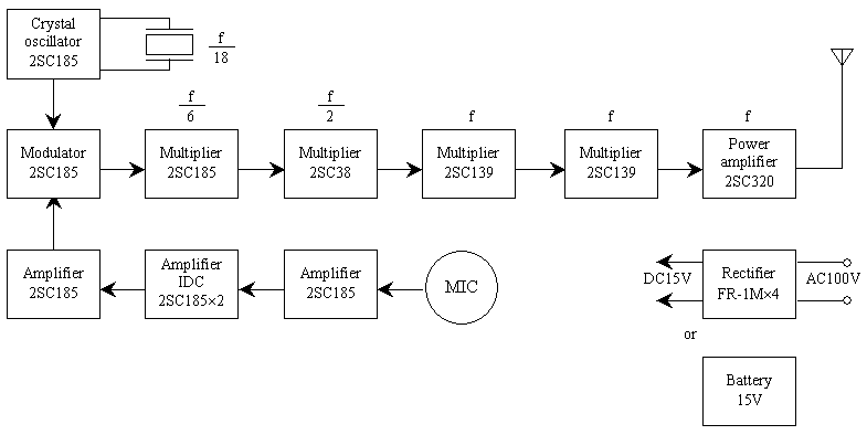
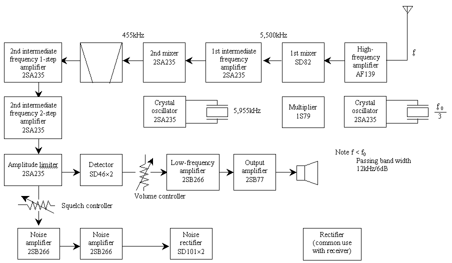
Radio equipment system diagram shall be as follows.
(1) In case of a system diagram relating to transmitting device, name and purpose of use of vacuum tube, semiconductor or integrated circuit, frequency in each stage, method of synthesizing frequency of emitted radio wave from oscillating frequency, and power supply voltage shall be entered.
(Entry example)
(2) In case of a system diagram relating to receiving device, name and purpose of use of vacuum tube, semiconductor or integrated circuit, frequency in each stage (including high/low relation between receiving frequency and frequency of first oscillator), and passing band width (which shall be 6dB or less) shall be entered.
(Entry example)
 |
- Type Specifications for radio equipment used for radio stations conducting radio navigation business and radio beaconing business
Type Specifications
| 1 Maximum measuring range |
|
2 Minimum measuring range |
|
 |
(1) Rated output |
|
(2) Type and frequency
range of emissive
radio wave |
|
(3) Oscillation |
|
(4) Modulation |
|
|
(5) Name of
manufacturer, etc |
Name of manufacturer |
Type or name |
Serial number |
| |
|
|
 |
(1) Passing band
width |
|
|
(2) Name of
manufacturer, etc. |
Name of manufacturer |
Type or name |
Serial number |
| |
|
|
 |
(1) Type and structure |
(2) Gain |
(3) Speed of rotation |
| |
|
|
|
(4) Width of angle of main radiation on
horizontal plane |
(5) Width of angle of main radiation on
vertical plane |
| |
|
|
6 Kind and type or name of attachment
|
|
7 Other types |
|
8 Attached drawing |
Radio equipment system diagram |
9 Matters for reference |
|
|
(JIS A4)
Short side
|
Notes:
- In the column 2, entry shall be made only in case of radio equipment mentioned in Item (33) of Article 8.
- In the column 3-(1), the standard value of output at the output terminal shown in the radio equipment system diagram shall be entered by type of wave. In the case where the rated output is decreased when using, the rated output, method of decreasing the rated output and the output after decrease shall be entered.
(Entry example) N0N 0.1W (using fixed attenuator, 0.01W)
- In the column 3-(2), an entry such as "N0N 10.525GHz" or "P0N 9410MHz" shall be made.
- In the column 3-(3), oscillation method and frequency shall be entered.
- In the column 3-(4), modulation frequency shall be entered only in the case where the type of radio wave entered in the column 3-(2) is A2N.
- In the columns 3-(5) and 4-(2), entry shall be made as follows.
(1) Name of manufacturer, etc. of transmitter shall be entered. However, in the case where transmitter and receiver are stored in a housing, entry shall be made only in the column 3-(5), and "same as transmitter" shall be entered in the column 4-(2).
(2) Entry of serial number is not required in the case where the applied equipment is not submitted pursuant to the proviso of Article 3 or 22, or in case of an application for certification by the type.
- In the column 4, a width that is 3dB or less shall be entered.
- In the column 5, if the antenna is not for common use for transmitter and receiver, whether for transmitter or receiver shall be identified in the column (1).
- In the column 5-(1), entry shall be made as follows.
(1) Plane of polarization (in case of circular polarized wave, the direction of rotation as seen from the transmission side shall be added) shall be entered, and if there are radiator, reflector, wave director, etc., their types and the number of elements shall be entered.
(2) With regard to parabolic reflector, electromagnetic horn, etc., diameter or length and breadth of each device shall be entered.
- In the column 5-(2), the value shall be indicated in Gis (absolute gain).
- In the column 5-(3), an entry such as "15 r.p.m" shall be made only in the case where the antenna is rotated when using.
- In the columns 5-(4) and 5-(5), all angles, including all directions in which the difference between the radiation power in the direction shown and the radiation power in the direction of maximum radiation is 3dB at the maximum, shall be entered.
- In the column 6, devices of the Applied Equipment not mentioned in columns 3 through 5 shall be entered.
- In the column 7, an entry shall be made to the effect that the types other than those mentioned in columns 1 through 6 meet the conditions specified in Chapter 3 of the Radio Law.
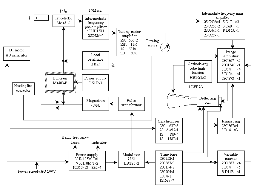
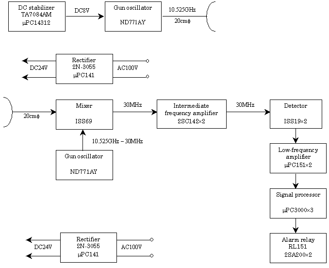
- In the radio equipment system diagram related to transmitter, name and purpose of use of vacuum tube, semiconductor or integrated circuit, frequency in each stage, method of synthesizing frequency of emitted radio wave from oscillating frequency, and power supply voltage shall be entered, and in the radio equipment system diagram related to receiver, name and purpose of use of vacuum tube, semiconductor or integrated circuit, and frequency in each stage (including high/low relation between receiving frequency and frequency of first oscillator) shall be entered.
(Entry example)
(1) In case of radio equipment used for ratio stations conducting radio navigation business
(2) In case of radio equipment used for radio stations conducting
radio beaconing business
 |
- Type Specifications for radio equipment used for radio stations of civil radio, radio stations of cordless telephones, specified low-power radio stations, radio stations of low-power security system, radio stations of low-power data communication system, radio stations of digital cordless telephones, land mobile stations of personal handyphone system (PHS), land mobile stations of electronic toll collection system, and radio stations of wireless card system.
Type Specifications
| 1 Communication system |
 |
(1) Rated output |
|
(2) Type and frequency
range of emissive
radio wave |
|
(3) Oscillation |
|
(4) Modulation |
|
|
3 Name of manufacturer, etc. |
Name of manufacturer |
Type or name |
Serial number |
| |
|
|
 |
(1) Type and structure |
(2) Gain |
| |
|
|
5 Kind and type or name of attachment
|
|
6 Other types |
|
7 Attached drawing |
Radio equipment system diagram |
8 Matters for reference |
|
|
(JIS A4)
Short side
|
Notes:
- In the column 1, an entry such as "simplex operation" or "duplex operation" shall be made. However, no entry is required in case of radio equipment used for specified low-power radio stations and which use radio wave of a frequency of over 2,425MHz to 2,475MHz, over 60GHz to 61GHz or over 76GHz to 77GHz.
- In the column 2-(1), the standard value of output at the output terminal shown in the radio equipment system diagram shall be entered by type of radio wave.
- In the column 2-(2), an entry such as "F1D 280.0000MHz, F3E 281.0000MHz through 282.0000MHz (12.5kHz intervals 81 waves)" shall be made.
- In the column 2-(3), oscillation method and frequency shall be entered.
| (Entry example) |
Crystal oscillation |
1/24 of the frequency applied for Technical Regulations Conformity Certification |
- In the column 2-(4), modulation method corresponding to the type of radio wave entered in the column 2-(2), maximum modulation frequency and maximum frequency deviation, etc. shall be entered. However, no entry is required in case of radio equipment used for radio stations of civil radio.
| (Entry example) |
F2D modulation method |
Frequency modulation, MSK modulation at signal transmitting speed of 1,200b/s (mark frequency 1,200Hz, space frequency 1,800Hz), maximum frequency deviation ±2.5kHz |
- In the column 3, entry of serial number is not required in the case where the Applied Equipment is not submitted pursuant to the proviso of Article 3 or 22, or in case of an application for certification by the type.
- In the column 4-(1), plane of polarization and the number of elements shall be entered in a way like "single antenna (V) ă/4". In case of radio equipment used for radio stations of civil radio, an entry such as "whip antenna ____ cm" shall be made.
- In the column 4-(2), the value shall be indicated by Gis (absolute gain). However, no entry is required in case of radio equipment used for radio stations of civil radio.
- In the column 5, devices of the Applied Equipment not mentioned in columns 2 and 3 shall be entered.
- In the column 6, an entry shall be made to the effect that the types other than those mentioned in columns 1 through 4 meet the conditions specified in Chapter 3 of the Radio Law.
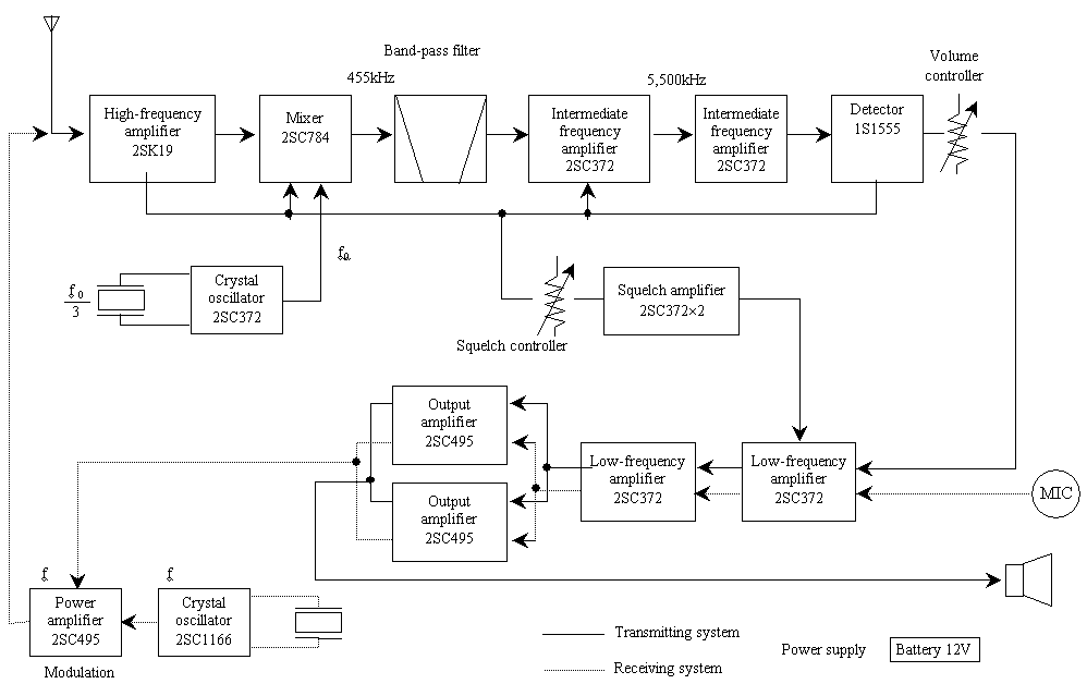
- In the radio equipment system diagram, name and purpose of use of semiconductor or integrated circuit, frequency in each stage (including frequency multiplying and synthesizing method), and power supply voltage shall be entered.
(Entry example)
 |
- Type Specifications for radio equipment used for amateur stations or simplified radio stations using radio wave of a frequency of 900MHz band or over 347.7MHz to 351.9MHz
Type Specifications
| 1 Communication system |
 |
(1) Rated output |
|
(2) Type and frequency
range of emissive
radio wave |
|
(3) Modulation |
|
|
3 Name of manufacturer, etc. |
Name of manufacturer |
Type or name |
Serial number |
| |
|
|
 |
(1) Type and structure |
(2) Gain |
| |
|
|
5 Kind and type or name of attachment
|
|
6 Other types |
|
7 Attached drawing |
Radio equipment system diagram |
8 Matters for reference |
|
|
(JIS A4)
Short side
|
Notes:
- In the column 1, an entry such as "simplex operation" or "diplex operation" shall be made.
- In the column 2-(1), the standard value of output at the output terminal shown in the radio equipment system diagram shall be entered.
- In the column 2-(2), an entry such as "A3J 430MHz band" shall be made in case of radio equipment used for amateur stations, an entry such as "F2D 903.0125MHz, F3E 903.0375MHz through 904.9875MHz (25kHz intervals 79 waves)" shall be made in case of radio equipment used for simplified radio stations using radio wave of a frequency of 900MHz band, an entry as "F2B F2C F2D F3C F3E 400MHz band" shall be made in case of radio equipment used for simplified radio stations using radio wave of a frequency of over 347MHz to 351.9MHz.
- In the column 2-(3), modulation method corresponding to the type of radio wave entered in the column 2-(2), maximum modulation frequency and maximum frequency deviation, etc. shall be entered.
| (Entry example) |
F2D modulation method |
| | |
Frequency modulation, MSK modulation at signal transmitting speed of 1,200b/s (mark frequency 1,200Hz, space frequency 1,800Hz), maximum frequency deviation ±3.5kHz |
| |
F3E modulation method |
| |
Frequency modulation, maximum modulation frequency 3,000Hz, maximum frequency deviation ±5kHz |
- In the column 3, entry of serial number is not required in the case where the Applied Equipment is not submitted pursuant to the proviso of Article 3 or 22, or in case of an application for certification by the type.
- In the column 4-(1), plane of polarization and the number of elements shall be entered in a way like "single antenna ă/4". However, no entry is required in case of radio equipment used for amateur stations.
- In the column 4-(2), the value shall be indicated in Gis (absolute gain). However, no entry is required in case of radio equipment used for amateur stations.
- In the column 5, call name memory device, indicator, etc. shall be entered.
(Entry example)
| Kind and type or name |
System, standard, etc. |
| Call name memory device |
| IC used | µP B403D, 14050B, 14020B |
| Memory capacity | 256 × 4bit |
|
- In the column 6, an entry shall be made to the effect that the types other than those mentioned in columns 1 through 4 meet the conditions specified in Chapter 3 of the Radio Law.
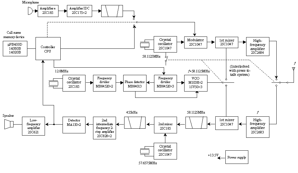
- In the radio equipment system diagram, name and purpose of use of semiconductor or integrated circuit, frequency in each stage (including frequency multiplying and synthesizing method), and power supply voltage shall be entered.
(Entry example)
 |
- Type Specifications for radio equipment used for earth stations or portable mobile earth stations
Type Specifications
| 1 Communication system |
 |
(1) Rated output |
|
(2) Type and frequency
range of emissive
radio wave |
|
(3) Oscillation |
|
(4) Modulation |
|
(5) Maximum power density |
| |
(6) High-frequency wave filter |
|
|
(7) Name of manufacturer, etc. |
Name of manufacturer |
Type or name |
Serial number |
| |
|
|
|
3 Type and frequency range of receivable radio wave of receiver |
|
 |
(1) Type and structure |
(2) Gain |
(3) Frequency |
| |
|
|
(4) Plane of polarization |
(5) Loss of feeder, etc. |
| |
|
|
5 Satellite tracking system |
|
6 Interlocking device |
|
7 Automatic emission stop system |
|
8 Kind and type or name of attachment |
|
9 Other types |
|
10 Attached drawing |
(1) Radio equipment system diagram
(2) Antenna directivity diagram |
11 Matters for reference |
|
(JIS A4)
Short side
Notes:
- In the column 1, an entry such as "duplex operation", "multiple operation" or "special communication system" shall be made, and signal transmitting speed such as "64kb/s" shall be added.
- In the column 2-(1), the standard value of output at the output terminal shown in the radio equipment system diagram shall be entered by type of radio wave.
- In the column 2-(2), an entry such as "G7E 14.3GHz through 14.4GHz" shall be made. In this case, for a transmitter of synthesizer type, the intervals and the number of waves of emissive frequency shall be added.
- In the column 2-(3), oscillation method and frequeycy, and frequency stability shall be entered. In case of multiplex radio equipment, etc. using two or more oscillators, entry shall be made for each oscillator. In this case, frequency stabilizing method shall be described if it is a special method.
- In the column 2-(4), modulation method corresponding to the type of radio wave entered in the column 2-(2) and the matters that apply according to the following classification shall be entered. In this case, type of passing signal shall be entered in the case where heterodyne trunking system is used, and in the case where energy diffusing device is used, its type, frequency and description of wave form shall be entered.
(1) Unshared frequency band width factor considering filter characteristic of transmitter
(2) Pulse width and repeated frequency
- In the column 2-(5), 4kHz band width of maximum spectrum power density shall be selected, and a value of full peak power within the band width converted per Hz shall be indicated in dBW/Hz.
- In the column 2-(6), for those inserted in the final stage of transmitter, type, the number of insertion steps and frequency characteristic shall be entered.
| (Entry example) | Butterworth type |
4th 2-step | ±8MHz/3dB decrease
±20MHz/50dB decrease |
- In the column 2-(7), entry shall be made as follows.
(1) Name of manufacturer, etc. of transmitter shall be entered.
(2) Entry of serial number is not required in the case where the Applied Equipment is not submitted pursuant to the proviso of Article 3 or 22, or in case of an application for certification by the type.
- In the column 3, entry shall be made according to Note 3.
- In the column 4, entry shall be made as follows.
(1) In the column 4-(1), diameter or length and breadth of parabolic reflector, electromagnetic horn, etc. shall be entered. In this case, if it is difficult to include all information because of complicated structure, an entry shall be made in this column to the effect that the structure is as shown in the attached drawing.
(2) In the column 4-(2), the value shall be indicated in Gis (absolute gain).
(3) In the column 4-(4), kind of plane of polarization shall be entered, and cross polarization discriminability of antenna shall be indicated in dB. In case of circular polarized wave, the direction of rotation of electric field vector as seen from the transmission side, that is either "right-handed rotation" or "left-handed rotation" shall be entered.
(4) In the column 4-(5), loss of feeder, etc. inserted between output terminal of transmitter and transmitting antenna and loss of feeder, etc. inserted between receiving antenna and input terminal of receiver shall be entered respectively.
- In the column 5, check either Yes or No with 3 depending on whether satellite tracking system (a system with the function of automatically tracking the direction of artificial satellite) is equipped or not.
- In the column 6, check either Yes or No with 3 depending on whether interlocking device (a device with the function of starting transmission only in the case where a control signal is received) is equipped or not.
- In the column 7, check either Yes or No with 3 depending on whether automatic emission stop system (a system with the function of automatically stopping emission of radio wave in the event of a trouble with the oscillation circuit) is equipped or not.
- In the column 8, devices of the Applied Equipment not mentioned in columns 2 through 7 shall be entered.
- In the column 9, an entry shall be made to the effect that the types other than those mentioned in columns 1 through 8 meet the conditions specified in Chapter 3 of the Radio Law.
- Entry, etc. in the attached drawing in the column 10 shall be as follows.
(1) The drawing (diagram) in the column 10-(1) shall describe system of transmitting device and receiving device, purpose of use and frequency of each system, and system interconnection of transmitting device and receiving device.
(2) The drawing (diagram) in the column 10-(2) shall describe directional characteristic of horizontal plane and vertical plane.

